Carbon cleaning and welding machine CC10 and CC15
We are manufacture of carbon cleaning machines from 7 year. CC10 is our new model. CC10 and CC15 are full profesional equipment for Carbon Cleaning of Engines in a garage or workshop.
- Power AC (V): 230V
- Power Consumption (kW / h): 1.8/2,5
- HHO Gas Output Max: 10 LPM – 600L/900L / Hour
- Max. Water Consumption (L / h): 0.20
- Water Refill: Manual
- Dimensions: (mm): 900 x 540 x 480 mm
- Weight: 60/80 KG
- Timer for Auto work 0-99 min. OFF if end working time.
- Control of quality of electrolyte
- Level gauge – show level of electrolyte if level is min. CC10 not run
- Voltage sensor if engine stoped CC10 OFF
- Presure sensor
- Warranty: 24 Months
Hydrogen generator B1 – Smoke killer
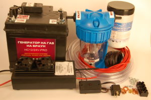
Multi-purpose Brawn’s Gas Generator HC12/24V-PRO
Usage: Hydrogen Generator (HHO-generator) suitable for cars, vans, trucks, agriculture and construction equipment powered by 1000 to 4000 cc engines.
The Hydrogen Engine complies with requirements of EU standards – it is laboratory tested and the conformity assessment procedure is executed according to Directive 2006/95-ЕС of the European Parliament. СЕ 2024 conformity marking is applied to our product.
Operating voltage: 12 V – 14 V
Current consumption: 10 А – 30 А
Productivity: 120 liter of Brawn’s gas per hour.
Fuel efficiency: 15% – 40%
Electrolyte freezing temperature: -25 degrees Celsius
Warranty: 24 months (observing all operating conditions)
All Brawn’s gas Generators manufactured by us are based on the HC12/24V Pro Model. The various models of Generators differ from one another in their input signals and sensors for control signals detection.
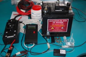
Scope of delivery of the Brawn’s Gas Generator:
- Hydrogen cell
- Magnetic sensor (for diesel ICE)/ Inductive sensor (for petrol ICE)
- Water filter/Expansion tank.
- PWM Process Controller
- Relay – 40А
- Cables
- Hoses
- Electrolyte
HHO cell HC12/24V Pro
1. Operating voltage – 11-14.02 V
2. Load current – 5 to 30 А
3. Operation temperature – 15 to +50 degrees
4. Level gauge current consumption: – <10 mA
5. Electrolyte concentration (KOH) – 10 – 14%
6. Productivity – up to 2 l/m of Brawn’s gas.
7. Overall dimensions (mm): H=220 , L=205 , W=175
8. Material
8.1.Casing – polypropylene
8.2. Electrodes – Steel 316L
The Electrolyzer is a device wherein process of electrolyze is conducted via an electrochemical method and so it results in the generation of “Brown’s gas”. The electrolyzer casing is made from polypropylene – a material with very good features of resistance to temperature variations, vibrations, loads and aggressive chemical media. It has form of classic accumulator. It consists of casing, top cover, connecting pieces, valve and level gauge.
Electrodes are positioned inside the Electrolyzer. Electrolyze is performed with their assist. The electrodes are made from steel grade 316L. Electrode power supply is provided by means of stainless steel stud pins – А2 (grade 304). For assembly stainless steel washers and nuts are used. For better electric conductivity out of casing, the washers and nuts used for tightening cable shoes of Electrolyzer power supply unit, are made from plain steel – galvanized.
Stickers are used to indicate holes and connection pieces purposes. The power supply terminals are designated with + and – signs directly encrusted in casing plastic material. An information sticker about product name and manufacturer information and contacts is attached to the Electrolyzer. The text is in Bulgarian and English.
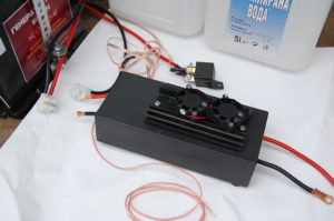
PWM / Process Controller PC12 for ННО – generator
1. Operating voltage 13/28 V
2. Working frequency – 1-3 kHz
3. Output current – <40А
4. Operation temperature – -15 to 80 degree Celsius
5. Adjusting method – Pulse Width Modulation
6. Frequency of revolution control signal -10-350 Hz
7.Control voltage – 0,8 – 4,5 V
8. Casing material – polystyrene
9. Dimensions (mm) – L=199,4, H=43,2, W=84
FULL AUTO Plug-n-Play PWM HHO CONTROLLER FOR HHO GENERATORS WITH INDICATION MODULE – dynamic adjustment, automatic operation.
HHO EFIE – simulator for Common Rail engine
In order to reach maximal efficiency after the installation of the HHO system it is necessary to mount a simulator of the sensor and throttle placed on the common combustion rail.
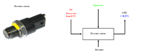
The signal wire from the sensor is discontinued and connected in series, respectively to terminals (3) and (4) – see fig. 3 and fig. 4. Terminals (1) and (2) of the simulator are connected in parallel (without being discontinued) to the wires of the throttle. The powering and mass wires to the sensor are not discontinued.
Signal wire: – The signal wire of the pressure sensor can be found (identify which of the three ones it is) by starting the car and then the voltage in it measured to mass should change within the limits from 0,5 to 4 volts, upon change of the rotations of the engine.
Powering wire (+ 5 volts) – The powering wire for the sensor can be found in the following way: the voltage between it and the mass (chassis) should be permanently 5 volts.
GND: – Attention should be paid that between the sensor mass and the minus terminal of the battery there is potential of 0,2V.
Note that voltage is measured by means of voltmeter for permanent voltage!
Chain description:
- blue – throttle + 12 volts
- brown – throttle -12 volts
- green – Input for the sensor signal (changes from 0,5 to 4 volts) (connects to the cut signal wire from the side of the voltage sensor)
- yellow – The outlet of the signal from the simulator is connected to the cut signal wire from the side of the electronic control unit (ECU)
- black – Mass (chassis) –(connection to the minus terminal of the battery)
- black with red line – +12V – (supplied +12 volts powering after contact)
- white and red – connected to the sensor mass without discontinuing it (0.2V).
Mode Signals Synchronizer for Process Controller Control
1. Power supply voltage: 12-14V
2. Output signal -voltage – 2-14V
3. Current consumption: <10 mА
This device is a entirely our development and it is revolutionary invention enchasing operation efficiency of Braun’s Gas Generator to some extend and allows accurately dosing of Brawn’s gas and its delivery to the engine. The synchronizing block serves to sum and controls the signals for PWM Process Controller regulation at two stages. We get two kinds of signals – signal for engine operation mode (the signal identify what the mode the engine running in the moment) and signal for engine load (this signal identify the engine load in the moment). These two signals are processed in the device and the device generates control signal to Process Controller. This control signal as most adequate as possible doses the Brawn’s gas quantity that is required for the purpose of achieving maximum efficiency.
Hydrogen Cell Optimizer
(The Optimizer is such device which functions resemble the function of turbine in ICE)
Hydrogen Cell Optimizer is a exclusively device that:
– improves efficiency of Brawn’s Gas Generator operation by approx. 20%;
– enhances hydrogen cell productivity by up to 15%;
– accelerates discharging of Brawn’s gas to the engine many times;
– enhances the dynamic of Brown’s gas engine;
– provides better HHO-gas adoption in the engine;
– reduces the temperature of operation of hydrogen cell;
– increases security;
It is recommended for vehicles with larger engine volumes and for such vehicles which are used for transport activities professionally – vans, buses, trucks and agriculture equipment.
Magnetic sensor – DN
(DU – sensor with increasing voltage of output signal, DN – sensor with decreasing voltage of output signal)
1. Power supply voltage: 12-14V
2. Output signal -voltage – 2-14V
3. Output signal frequency – 30 – 350 Hz
4.Current consumption: <10 mА
Revolution sensors DU and DN are devices reading the vehicle engine revolutions and sending control signals to Process controller. The revolution sensor is a device for detection of variations in the magnetic field in front of detecting element. Against the sensor some magnets are fixed on the any of engine washers, this one turning proportional to the crankshaft revolutions. When the magnets pass before the sensor they change the magnetic field. The sensor detects these changes and generates frequency and voltage signals which control the process controller. The sensor is installed in plastic casing. Light indicator indicating controller operation mode is installed on the casing cover. It supplies from the car accumulator directly in order to prevent interference and voltage picks during the car engine operation.
Inductive sensor for control by signals coming from spark plugs
The inductive sensor is intended to read operating mode of petrol engines through signals generated by inductance from the spark plugs cable. The devise is intended to use on petrol engines. Silicone cable is wrapped around the any of spark plug cables and voltage is induced in the silicone cable. The sensor reads this voltage as frequency signal. The signal converts in voltage for control of Process controller operation. In this way when engine revolutions are increased the production of Brown’s gas that goes to the engine is regulated.
1. Power supply voltage: 12-14V
2. Output signal -voltage – 2-14V
3. Output signal frequency – 30 – 350 Hz
4. Current consumption: <10 mА
Level gauge – LM1
1. Power supply voltage – 12-14V
2. Current consumption :< 10ma
The Level gauge is electronic device to indicate the level of electrolyte in the Electrolyzer. There are two light indicators – red and green. The green light indicator indicates maximum electrolyte level in the hydrogen cell. If the red light indicator goes on then it is required adding immediately distiller water in the hydrogen cell. In case of both light indicators are off, the level is normal.
CAUTION: Check the level only when the hydrogen cell is supplied (When the car is at the contact and power supply voltage is delivered to hydrogen cell). Otherwise the red indicator will be on and these will be no mean that the level is low but only that no supplying to the Generator.


